Optical Fibers and Cavities 光纤与腔体
Michael <br> Physics and Astronomy Department, UCLA, Los Angeles, California 90024, USA
(Dated: March 9, 2025)
迈克尔·余<br> 美国加州大学洛杉矶分校物理与天文系,洛杉矶,加利福尼亚 90024,美国
(日期:2025年3月9日)
Abstract 摘要
Optical fibers and cavities are delicate systems that can be used to transmit light and trap standing waves respectively with a wide range of modern applications in communication, networks and research. While these optical systems can be readily analyzed theoretically, they can be a challenge to construct in a lab for the inexperienced. In this paper we will be exploring the mechanics behind optical fibers and cavities, their transmission and stability requirements and how they can be constructed using complex beam parameter and ray transfer matrix analysis.
光纤和腔体是精密的系统,分别用于传输光和捕获驻波,在现代通信、网络和研究中有广泛应用。虽然这些光学系统在理论上很容易分析,但对于没有经验的人来说,在实验室中构建它们可能是一个挑战。本文将探讨光纤和腔体背后的力学原理、它们的传输和稳定性要求,以及如何使用复光束参数和光线传输矩阵分析来构建它们。
I. INTRODUCTION 引言
Optical fibers and cavities are powerful devices that have numerous applications both inside the laboratory and in everyday life. Optical fibers utilize the principle of total internal reflection to guide and transmit light between two ends of the fiber and is widely used in modern fiber-optic communications and computer networking. Inside the lab, optical fibers serve as a means of easily transmitting light and power as well as sensors that can detect changes on the fiber through changes in the interference pattern and intensity. Optical cavities, on the other hand, trap standing waves inside an arrangement of mirrors by matching longitudinal and transverse modes and are a critical component in modern lasers.
光纤和腔体是功能强大的设备,在实验室和日常生活中都有广泛应用。光纤利用全内反射原理在光纤两端之间引导和传输光,广泛应用于现代光纤通信和计算机网络。在实验室中,光纤不仅可以轻松传输光和功率,还可以作为传感器,通过干涉图样和强度的变化来检测光纤上的变化。另一方面,光学腔体通过匹配纵向和横向模式,在镜片排列中捕获驻波,是现代激光器的关键组件。
Here, optical fibers and cavities will be used not only to study the evolution of light as it traverses through optical elements but also as a means of gaining experimental experience in mode matching. Optical fibers and cavities are in general very sensitive to the geometry of the beam that enters the device. As we shall see, for optical fibers, only certain modes of the beam incident on the core are propagated through the fiber so it is crucial that the beam is well aligned and matches the geometry of the input fiber. As for optical cavities, both longitudinal and transverse modes must match the cavity setup to produce standing Gaussian modes in the device.
在这里,光纤和腔体不仅用于研究光在穿过光学元件时的演变,还用于获得模式匹配的实验经验。光纤和腔体通常对进入设备的光束的几何形状非常敏感。正如我们将看到的,对于光纤,只有入射到纤芯的光束的某些模式才能通过光纤传播,因此光束必须良好对准并与输入光纤的几何形状匹配。对于光学腔体,纵向和横向模式都必须与腔体设置匹配,才能在设备中产生驻高斯模式。
The remainder of the paper will be structured as follows. Section II will provide a brief background on the theory of Gaussian beam evolution as it propagates through free space and through optical elements such as lenses and mirrors. Section III will discuss the setups and results for the multimode and singlemode fiber. Section IV will discuss mode matching for optical cavities and the experimental results produced in the lab. Section V will conclude. Additional supplementary information can be found in the appendix.
本文的其余部分结构如下。第二部分将简要介绍高斯光束在自由空间和光学元件(如透镜和镜片)中传播时的演变理论。第三部分将讨论多模和单模光纤的设置和结果。第四部分将讨论光学腔体的模式匹配以及在实验室中产生的实验结果。第五部分将得出结论。更多补充信息可以在附录中找到。
II. THEORY 理论
A. Ray Transfer Matrices 光线传输矩阵
As the name suggests, ray transfer matrices (also known as ABCD matrices) are commonly used to describe the evolution of ray optics as the beam propagates through an optical system. An optical ray under the paraxial approximation, where all rays travel at small angles relative to the optical axis such that , can be uniquely characterized by its slope and displacement relative to the optical axis in vector form , see fig 1 .
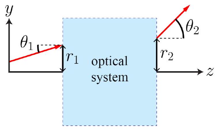
顾名思义,光线传输矩阵(也称为ABCD矩阵)通常用于描述光线光学在光束通过光学系统时的演变。在傍轴近似下,所有光线都以相对于光轴的小角度传播,使得,光线可以唯一地由其斜率和相对于光轴的位移以向量形式表示,见图1。
FIG. 1. Ray optics under the paraxial approximation: . Here the ray enters the optical system with displacement and slope and leaves the optical system at displacement and slope . The vectors that describe these rays are and respectively.
图1. 傍轴近似下的光线光学: 。这里光线以位移和斜率进入光学系统,并以位移和斜率离开光学系统。描述这些光线的向量分别是和。
As the ray propagates through free space and through optical elements, its evolution can be characterized by simple matrix multiplication of the corresponding ray transfer matrix. As an example, consider a ray with initial displacement and slope that traverses in free space a distance L. After it propagates a distance d, simple geometry tells us that the displacement and slope are now and respectively. This behavior is characterized by the ray transfer matrix for free space propagation of distance L:
当光线在自由空间和光学元件中传播时,其演变可以通过相应的光线传输矩阵的简单矩阵乘法来描述。例如,考虑一个初始位移为、斜率为的光线,它在自由空间中传播距离L。在传播距离d后,简单的几何告诉我们,位移和斜率现在分别是和。这种行为由自由空间传播距离L的光线传输矩阵描述:
Where the ray vector after applying the free propagation transfer matrix is as described above.
应用自由传播传输矩阵后的光线向量为,如上所述。
Next, let us evaluate the ray transfer matrix as the beam passes through a thin lens of focal length f. Under the thin lens approximation, the displacements of the ray as it enters and exits the lens is the same: such that and for the ray transfer matrix of the form . From ray optics, we know that light parallel to the optical axis will cross the optical axis a distance f from the lens. That is, the slope of the emerging ray must be and correspondingly . Furthermore, a ray that crosses the optical axis a distance behind the lens will cross the optical axis again a distance 2 f after the lens in what is commonly known as the imaging rule such that if , the slopes will be equal and opposite: . Now with , and , we can substitute this into the general equation and uniquely determine that . That is, the ray transfer matrix of a thin lens with focal length f is:
接下来,让我们评估光束通过焦距为f的薄透镜时的光线传输矩阵。在薄透镜近似下,光线进入和离开透镜时的位移相同:,因此光线传输矩阵中的和。根据光线光学,我们知道平行于光轴的光将在距离透镜f处穿过光轴。也就是说,出射光线的斜率必须为,相应地。此外,在透镜后方距离处穿过光轴的光线将在透镜前方距离2 f处再次穿过光轴,这就是通常所说的成像规则,因此如果,斜率将相等且相反:。现在,有了、和,我们可以将其代入一般方程,并唯一确定。也就是说,焦距为f的薄透镜的光线传输矩阵为:
The powerful aspect behind the ray transfer matrix formalism is that these transfer matrices can be composed to describe any complicated optical system through simple matrix multiplication. For instance, if are the sequential ray transfer matrices of optical elements in a complex optical system, the entire system can be described by a single transfer matrix: .
光线传输矩阵形式的强大之处在于,这些传输矩阵可以通过简单的矩阵乘法来描述任何复杂的光学系统。例如,如果是复杂光学系统中光学元件的连续光线传输矩阵,则整个系统可以用一个单一的传输矩阵来描述:。
B. Complex Beam Parameter 复光束参数
In this lab, and generally in practice, the rays produced by lasers are characterized by a Gaussian beam with width w and radius of curvature R that both evolve as the beam propagates along optical axis z, fig 3. These parameters are often uniquely characterized by a single complex beam parameter at any distance along the optical axis:
在本实验室中,通常激光器产生的光线由高斯光束表征,其宽度w和曲率半径R随着光束沿光轴z传播而变化,见图3。这些参数通常由沿光轴任意距离处的单一复光束参数唯一表征:
where we see that information about the radius of curvature and waist are stored in the real and imaginary components of respectively. As the beam with initial complex beam parameter q traverses through an optical system described by the ray transfer matrix , it turns out that the complex beam parameter q' as the beam exits the system is described by
from which the new radius of curvature and waist can be computed by matching the real and imaginary components with equation 3 .
在这里,我们看到曲率半径和束腰的信息分别存储在的实部和虚部中。当具有初始复光束参数q的光束通过由光线传输矩阵描述的光学系统时,光束离开系统时的复光束参数q'由上式描述。通过匹配实部和虚部与方程3,可以计算出新的曲率半径和束腰。
III. OPTICAL FIBERS 光纤
A. Theory 理论
Optical fibers are thin, flexible fibers in which light can be transmitted between the two ends of the fiber. The optical fibers in this lab and the vast majority in use are what is known as a step index fiber that consists of a cylindrically symmetric core of radius a and refractive index surrounded by a cladding of lower refractive index . The idea behind step index fibers is that light entering at the higher refractive index fiber core at near incident angles will experience full internal reflection as it hits the lower refractive index cladding. By continually experiencing full internal reflections in the fiber core, the light is guided through the fiber until it exits on the other end. Let us derive the necessary conditions for which light will be guided through the step index fiber.
光纤是细长、柔韧的纤维,可以在其两端之间传输光。本实验室中使用的光纤以及绝大多数实际应用中的光纤被称为阶跃折射率光纤,它由一个半径为a、折射率为的圆柱对称纤芯组成,周围包裹着折射率较低的的包层。阶跃折射率光纤的原理是,以接近入射角进入较高折射率纤芯的光在遇到较低折射率包层时会发生全内反射。通过在纤芯中不断发生全内反射,光被引导通过光纤,直到从另一端射出。让我们推导光在阶跃折射率光纤中传播的必要条件。
From the discussion above, the first condition that must be satisfied is that incoming light must hit the smaller fiber core in the center. Suppose that the incoming light is incident on the core at some angle from the air with refractive index , see fig 4 . Applying Snell's law at the interface between the air and the fiber core,
根据上述讨论,必须满足的第一个条件是入射光必须击中中心较小的纤芯。假设入射光以的角度从折射率为的空气中入射到纤芯上,见图4。在空气和纤芯的界面处应用斯涅尔定律,得到上式。
Now applying Snell's law at the interface between the core and the cladding, we have . In order to achieve total internal reflection, we want such that and substituting into equation 5 , we find the total internal reflection condition for the initial incident angle is
现在在纤芯和包层的界面处应用斯涅尔定律,得到 。为了实现全内反射,我们希望,使得,将其代入方程5,我们得到初始入射角的全内反射条件为上式。
That is, for all incident light at angle less than or equal to , the light will be guided through the step index fiber.
也就是说,对于所有入射角小于或等于的入射光,光将被引导通过阶跃折射率光纤。
B. Setup 设置
From the earlier discussion, in order to guide the maximum amount of light through a step index fiber we should aim to design an optical system in which the beam as it hits the step index fiber is both well within the core diameter and at an angle less than the critical angle from equation 6 . In order to ensure that the beam lies entirely within the fiber core, we want to ensure that the beam waist is smaller than the fiber core radius. To ensure that the beam is incident at a critical angle to experience total internal reflection inside the fiber, the beam should be a.) aligned parallel to the fiber and b.) have a large radius of curvature. The radius of curvature requirement is important as it ensures that rays near the Gaussian beam edge are also within the critical angle.
根据前面的讨论,为了通过阶跃折射率光纤引导最大量的光,我们应该设计一个光学系统,使得光束在击中阶跃折射率光纤时既在纤芯直径内,又小于方程6中的临界角。为了确保光束完全位于纤芯内,我们希望确保束腰小于纤芯半径。为了确保光束以临界角入射,以便在光纤内发生全内反射,光束应该:a.) 与光纤平行对齐,b.) 具有较大的曲率半径。曲率半径的要求很重要,因为它确保高斯光束边缘附近的光线也在临界角内。
While there are many designs that could create a Gaussian beam with small waist and high radius of curvature, perhaps the easiest and most straightforward optical system to accomplish this is through an optical telescope consisting of two lenses separated by the sum of their focal lengths. The optical telescope can be designed to squeeze the waist of the incoming beam by a factor where are the focal lengths of the first and second lenses respectively. The Gaussian beam that leaves the cavity now has a smaller waist and after propagating for another distance will be minimized at the minimum waist location with infinite radius of curvature. By placing the step index fiber at the minimum waist location after the telescope, the beam can be designed to be narrow enough to completely enter the core and aligned such that all the rays are within the critical angle (even those at the beam edge as the radius of curvature is infinite).
虽然有许多设计可以创建具有小束腰和高曲率半径的高斯光束,但最简单直接的光学系统可能是通过一个光学望远镜来实现的,该望远镜由两个透镜组成,它们之间的距离为它们的焦距之和。光学望远镜可以将入射光束的束腰压缩倍,其中分别是第一个和第二个透镜的焦距。离开腔体的高斯光束现在具有较小的束腰,并且在传播另一个距离后,将在最小束腰位置处达到最小值,且具有无限的曲率半径。通过将阶跃折射率光纤放置在望远镜后的最小束腰位置,可以将光束设计得足够窄,以完全进入纤芯,并且对齐,使得所有光线都在临界角内(即使光束边缘的光线也是如此,因为曲率半径是无限的)。
C. Multimode 多模
The multimode fiber we will be coupling light into is the ThorLabs M43L01 multimode fiber with a core diameter of . Attached to both ends of the multimode fiber are CFC-8X-B adjustable collimators with a focal length of 7.5 mm . The collimators serve to a.) provide additional adjustable degrees of freedom to facilitate laser alignment and b.) to further focus the beam into the fiber core.
我们将耦合光的多模光纤是ThorLabs M43L01 多模光纤,其纤芯直径为。多模光纤的两端连接有CFC-8X-B可调准直器,其焦距为7.5 mm。准直器的作用是:a.) 提供额外的可调自由度,以便于激光对准,b.) 进一步将光束聚焦到纤芯中。
From the theory of step index fiber coupling discussed above, we are looking to design an optical system in which the Gaussian beam has a minimum waist of approximately .052 mm at the multimode fiber core. For a laser source with minimum waist of approximately .45 mm , we designed the optical system such that a 200 mm focal length lens is placed 10 cm after the laser source, followed by a 100 mm lens 30 cm after the first lens and finally the multimode fiber with the 7.5 mm collimator 12.5 cm after the second lens at which the minimum beam waist is located after the optical telescope. Additional details and relevant code can be found in the attached files.
根据前面讨论的阶跃折射率光纤耦合理论,我们正在设计一个光学系统,使得高斯光束在多模光纤纤芯处的最小束腰约为0.052 mm。对于最小束腰约为0.45 mm的激光源,我们设计的光学系统如下:在激光源后10 cm处放置一个200 mm焦距透镜,然后在第一个透镜后30 cm处放置一个100 mm透镜,最后在第二个透镜后12.5 cm处放置带有7.5 mm准直器的多模光纤,最小束腰位于光学望远镜之后。更多细节和相关代码可以在附加文件中找到。
The beam waist just before the collimator is approximately .225 mm . Unfortunately, the exact distance between the collimator lens and the multimode core is unknown. However, a rough estimate of 5 mm separation suggest that the waist as the beam enters the multimode fiber is approximately .075 mm which is just around the desired waist of .052 mm . The actual value will vary depending on the precise distance between the collimator lens and multimode core, but our estimates suggest a theoretical coupling efficiency of around . After fine adjustments in the system to maximize the laser and fiber alignment, we obtained a transmission of 6.58 V from a maximum of 9.2 V before the optical fiber which is a coupling efficiency of around 71.5 percent. Although this experimental value is higher than the theoretical maximum, again we stress that the theoretical maximal coupling efficiency cannot be determined precisely without the precise distance between the collimator and fiber. The theoretical value we report is a rough estimate used mainly to gauge how well our optical system was designed.
准直器前的束腰约为0.225 mm。不幸的是,准直器透镜和多模纤芯之间的确切距离未知。然而,粗略估计5 mm的间距表明,光束进入多模光纤时的束腰约为0.075 mm,接近所需的0.052 mm。实际值将根据准直器透镜和多模纤芯之间的精确距离而变化,但我们的估计表明理论耦合效率约为。在系统中进行微调以最大化激光和光纤对准后,我们获得了6.58 V的传输,而光纤前的最大值为9.2 V,耦合效率约为71.5%。尽管这个实验值高于理论最大值,但我们再次强调,如果没有准直器和光纤之间的精确距离,理论最大耦合效率无法精确确定。我们报告的理论值是一个粗略估计,主要用于评估我们的光学系统设计得如何。
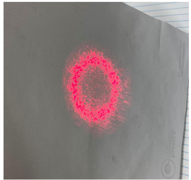
FIG. 5. Multimode optical fiber transmission at 71.5 percent efficiency. The ring pattern is a result of total internal reflection between the fiber core and cladding.
图5. 多模光纤传输效率为71.5%。环状图案是纤芯和包层之间全内反射的结果。
D. Singlemode 单模
The singlemode optical fiber we will be coupling light into is the ThorLabs P1-630A-FC-2 with a core diameter of . Unlike the multimode fiber, the singlemode fiber has a much smaller core diameter so that only a single mode can be coupled and transmitted in the fiber. To assist with beam alignment and focus on the tiny core, the 7.5 mm focal length collimator will again be attached to the optical fiber ends.
我们将耦合光的单模光纤是ThorLabs P1-630A-FC-2,其纤芯直径为。与多模光纤不同,单模光纤的纤芯直径要小得多,因此只能耦合和传输单一模式。为了帮助光束对准并聚焦在微小的纤芯上,7.5 mm焦距准直器将再次连接到光纤末端。
It can be shown that a plane wave with waist incident on a thin lens of focal length will have its minimum waist at a distance
可以证明,具有束腰的平面波入射到焦距为的薄透镜上时,其最小束腰将出现在一定距离处。
from the lens where is the confocal parameter of the input beam. The minimum waist size at this location can similarly to shown to be
从透镜开始,其中是输入光束的共焦参数。该位置的最小束腰尺寸同样可以表示为:
Substituting the parameters for the collimator and the desired minimum waist at the singlemode fiber core of 7.5 mm and respectively, we find that the waist of the beam just before the collimator should be approximately .68 mm which is just a bit larger than the laser source of .45 mm . Gaussian beams expand naturally as they propagate through free space, so we determined that the best optical system that would produce the desired waist is to just allow the beam to propagate without any optical elements. Under this optical system, the beam would achieve the desired waist after propagating 1.159 m . Relevant code to this derivation can be found in the attached files.
将准直器的参数和单模光纤纤芯处所需的最小束腰分别为7.5 mm和代入,我们发现光束在准直器前的束腰应约为0.68 mm,略大于激光源的0.45 mm。高斯光束在自由空间中传播时会自然扩展,因此我们确定,产生所需束腰的最佳光学系统是让光束在没有任何光学元件的情况下传播。在这种光学系统下,光束在传播1.159 m后将达到所需的束腰。相关推导代码可以在附加文件中找到。
Setting the collimator and singlemode fiber 1.159 m from the laser source and optimizing for alignment, we found that only a tiny portion of the original beam was successfully transmitted through the fiber. It turns out the problem was that the minimum beam waist size from equation 8 is only true at a distance 7 away from the lens. That is, we cannot assume that the collimator and optical fiber are separated by distance at which the minimum waist size occurs, especially if we do not know precisely what this distance is as discussed earlier in the multimode coupling.
将准直器和单模光纤放置在距离激光源1.159 m处并进行对准优化后,我们发现只有一小部分原始光束成功通过光纤传输。问题在于,方程8中的最小束腰尺寸仅在距离透镜7处成立。也就是说,我们不能假设准直器和光纤之间的距离为,即最小束腰尺寸出现的位置,特别是如果我们不知道这个距离的确切值,正如之前在多模耦合中讨论的那样。
By adding a 300 mm focal length lens 30 cm before the collimator to focus the beam, we were able to get much better light transmission. We measured a transmission of 321 mV from an original beam intensity of 11 V from the photodiode for an efficiency of approximately 3 percent. Based off this result, we conclude that the collimator and optical fiber separation is much less than the distance at which the minimum beam waist occurs. The beam that hits the optical fiber clearly has a much larger waist than the the core radius in our original setup without the lens resulting in a nonexistant coupling efficiency. This is a result of the separation distance of the collimator and optical fiber either being much less or much greater than the minimum beam waist separation . By focusing the beam before it enters the collimator and seeing a drastic improvement to the efficiency, it is clear that the former is the case.
通过在准直器前30 cm处添加一个300 mm焦距透镜来聚焦光束,我们能够获得更好的光传输。我们测量到来自光电二极管的传输为321 mV,而原始光束强度为11 V,效率约为3%。基于这一结果,我们得出结论,准直器和光纤之间的距离远小于最小束腰出现的位置。在没有透镜的原始设置中,击中光纤的光束的束腰明显大于纤芯半径,导致耦合效率几乎为零。这是由于准直器和光纤之间的分离距离要么远小于,要么远大于最小束腰分离。通过在光束进入准直器之前对其进行聚焦,并看到效率的显著提高,很明显是前一种情况。
Unfortunately due to time constraints we were unable to fully optimize for the singlemode coupling efficiency. However, based off our findings we would design a system similar to the multimode that utilizes an optical telescope to focus the beam and reduce waist size given additional time. An improvement to future fiber coupling labs would be to accurately measure or to find online the precise distance between the collimator lens and the optical fiber. This way we can more accurately generate the appropriate Gaussian beam parameters to maximize coupling without guessing in the dark. Furthermore, due to the lower than desired coupling efficiency of just 3 percent, we were unable to explore how changes in the optical fiber affect the transmitted polarizations since the beams after the beamsplitter were too faint to detect.
遗憾的是,由于时间限制,我们无法完全优化单模耦合效率。然而,基于我们的发现,如果有更多时间,我们会设计一个类似于多模的系统,利用光学望远镜来聚焦光束并减小束腰尺寸。对未来光纤耦合实验的改进将是准确测量或在线查找准直器透镜和光纤之间的精确距离。这样,我们可以更准确地生成适当的高斯光束参数,以最大化耦合,而不是在黑暗中猜测。此外,由于耦合效率仅为3%,低于预期,我们无法探索光纤的变化如何影响传输的偏振,因为分束器后的光束太微弱而无法检测。
IV. OPTICAL CAVITIES 光学腔
A. Theory 理论
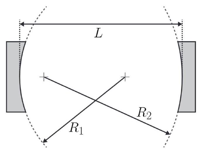
FIG. 6. Optical cavity consisting of 2 concave mirrors with radii of curvature and respectively separated by distance L.
图6. 光学腔由两个凹面镜组成,其曲率半径分别为和,相距距离L。
Optical cavities are characterized by a system of two mirrors with radius of curvatures and separated by some distance in which stable Gaussian modes can reside, fig 6 . In order for a stable cavity to be formed, the Gaussian beam inside the cavity must be resonant both longitudinally (where the length of the cavity is some integer multiple of the wavelength such that constructive interference may occur) and transversely (field pattern in the plane perpendicular to the direction of propagation, ie modes). These conditions will be met if the transformation of the q parameter of the Gaussian beam after a full round trip remains unchanged. That is, for complex beam parameter at some location z in the cavity and ray transfer matrix describing a full round trip beginning at z and ending at , the stability condition requires
光学腔的特征是由两个镜子组成的系统,其曲率半径分别为和,相距距离,其中可以存在稳定的高斯模式,如图6所示。为了形成一个稳定的腔体,腔体内的高斯光束必须在纵向(腔体的长度是波长的某个整数倍,以便发生相长干涉)和横向(垂直于传播方向的平面中的场模式,即模式)上都共振。如果高斯光束的q参数在完整的往返后保持不变,这些条件将得到满足。也就是说,对于腔体中某个位置z的复光束参数,以及描述从z开始并结束于的完整往返的光线传输矩阵,稳定性条件要求:
Solving for , we find that this condition can be expressed as
求解,我们发现这个条件可以表示为:
Now to determine the ray transfer matrix that describes a full round trip in a cavity, suppose the beam begins at one mirror with radius of curvature . A full round trip in the cavity would begin with free space propagation by distance , reflection off mirror with radius of curvature , free space propagation back by distance L before a final reflection off the initial mirror with radius of curvature . The ray transfer matrix that describes this system is
现在,为了确定描述腔体中完整往返的光线传输矩阵,假设光束从曲率半径为的镜子开始。腔体中的完整往返将从自由空间传播距离开始,然后反射曲率半径为的镜子,再自由空间传播返回距离L,最后反射曲率半径为的初始镜子。描述这个系统的光线传输矩阵是:
where we have used that the ray transfer matrix of a reflection off a curved mirror with radius of curvature R is . The proof does not contribution to the discussion and interested readers are encouraged to consult undergraduate optics texts.
我们使用了曲率半径为R的曲面镜反射的光线传输矩阵为。证明对讨论没有贡献,感兴趣的读者可以参考本科光学教材。
Combining equations 10 and 7 , the cavity will be stable if the q parameter of the Gaussian beam is exactly
结合方程10和7,如果高斯光束的q参数恰好为以下值,腔体将是稳定的:
at the mirror with radius of curvature where is the distance of the minimum waist (with respect to the mirror) and b is the confocal parameter.
在曲率半径为的镜子处,其中是最小束腰(相对于镜子)的距离,b是共焦参数。
 FIG. 7. The setup for a bowtie cavity with a single concave mirror, a silvered mirror and two backside polished mirrors in the input/output. Unlike standard cavities, the bowtie cavity utilizes only a single concave mirror from which the beam traverses in a bowtie pattern before hitting the concave mirror again.
图7. 蝴蝶结腔的设置,包括一个凹面镜、一个镀银镜和两个背面抛光镜用于输入/输出。与标准腔体不同,蝴蝶结腔仅使用一个凹面镜,光束在蝴蝶结图案中传播,然后再次击中凹面镜。
B. Setup 设置
For this lab, we implemented an optical cavity following the bowtie design in figure 7. Unlike traditional cavities, the bowtie design uses only a single mirror with cavity length equal to the sum of the bowtie path. Since the same mirror is used at both 'ends' of the cavity, the radius of curvature are the same such that we can write equation 12 as
在这个实验中,我们按照图7中的蝴蝶结设计实现了一个光学腔。与传统的腔体不同,蝴蝶结设计仅使用一个镜子,其腔体长度等于蝴蝶结路径的总和。由于在腔体的两端使用相同的镜子,曲率半径相同,因此我们可以将方程12写为:
Now matching the parameter at the cavity mirror can pose to be quite the challenge as both the real and imaginary components of must match. Instead, we can match the parameter at the minimum beam waist inside the cavity, which according to equation 12 is located at (exactly halfway between the mirrors or in the case of the bowtie cavity at the input back-polished mirror) with minimum waist
现在,匹配腔体镜处的参数可能是一个相当大的挑战,因为的实部和虚部都必须匹配。相反,我们可以匹配腔体内最小束腰处的参数,根据方程12,它位于处(正好在镜子之间,或者在蝴蝶结腔的情况下位于输入背面抛光镜处),其最小束腰为:
That is, right when the laser enters the cavity at the input back-polished mirror (lower left mirror in 7), we want the q parameter of the Gaussian beam to be
也就是说,当激光在7中所示的左下方镜子处通过输入背面抛光镜进入腔体时,我们希望高斯光束的q参数为
where is the minimum beam waist as given by equation 14.
其中是由方程14给出的最小束腰。
C. Optical System Design 光学系统设计
To form a stable cavity in which we can generate transverse modes, we want to create an optical system that will generate the q parameter in equation 15. To accomplish this, we begin by measuring minimum beam waist of the laser. We can approximate the Gaussian beam waist at any point in the laser path by measuring the intensity of the beam with portions blocked by a flat edge and fitting the data to where w is the beam waist at that location and x is the position of the edge in the beam. For a detailed derivation, see the appendix IV D. We performed these intensity measurements near the laser output and produced the following fit
为了形成可以产生横向模式的稳定腔体,我们需要创建一个能产生方程15中q参数的光学系统。为此,我们首先测量激光的最小束腰。我们可以通过用平边缘遮挡部分光束并测量光束的强度,然后将数据拟合到来近似激光路径上任意点的高斯光束束腰,其中w是该位置的束腰,x是边缘在光束中的位置。详细推导见附录IV D。我们在激光输出附近进行了这些强度测量并得到了以下拟合结果
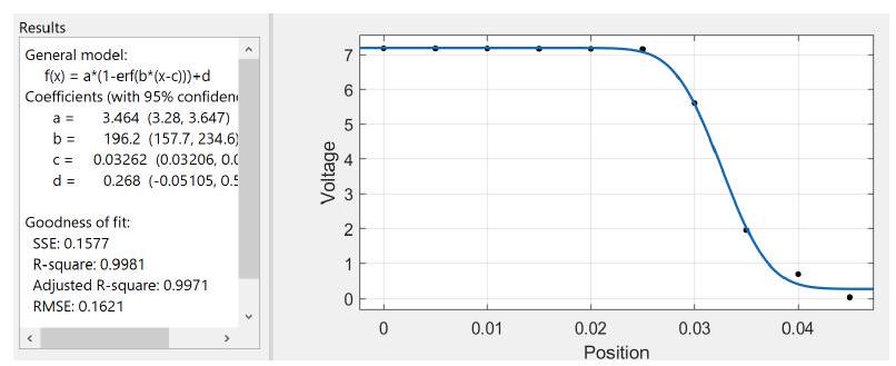
FIG. 8. Intensity cutoff measurements to determine minimum waist of laser. The x axis is the position of the flat edge in units of inches. The y axis is the voltage measurement of the photodiode.
图8. 用强度截止测量来确定激光的最小束腰。x轴是平边缘的位置,单位为英寸。y轴是光电二极管的电压测量值。
From the fit, the minimum waist is approximately inches or equivalently .0001832 meters where . Since the measurement was performed a short distance from the laser, the actual minimum waist at the laser front is a bit smaller. However, the laser is well collimated so the beam will not have diverged much a short distance from the source.
从拟合结果看,最小束腰约为英寸或等效的0.0001832米,其中。由于测量是在距离激光很短距离处进行的,激光前端的实际最小束腰会稍小一些。不过,激光准直性很好,所以光束在距离光源很短的距离内不会发散太多。
Now that we have the laser minimum waist, we want to design an optical system that will produce a Gaussian beam with q parameter as in equation 15. The actual design depends heavily on the available optical elements, the laser source and the desired cavity dimensions. Our cavity in particular was restricted to a concave mirror with a 1 meter radius of curvature and was designed such that the width of the bowtie cavity was longer than the height since mirrors operate best at small angles of incidence. For our chosen cavity parameters and the desired minimum waist at the input back-polished mirror of the cavity is .000215 m using equations 14 and 15. Since this is larger than the laser minimum waist of .0001832 m, we utilized a reverse telescope with lenses of focal lengths 75 mm and 200 mm to first expand the beam. The code used to design the appropriate optical system can be found in the attached files and the exact setup with relevant distances are displayed in figure 9.
现在我们已经有了激光最小束腰,我们要设计一个能产生具有方程15中q参数的高斯光束的光学系统。实际设计在很大程度上取决于可用的光学元件、激光源和所需的腔体尺寸。我们的腔体特别受限于一个曲率半径为1米的凹面镜,并且设计时蝴蝶结腔的宽度大于高度,因为镜子在小入射角下工作效果最好。对于我们选择的腔体参数 和 ,使用方程14和15计算得到腔体的输入背面抛光镜处所需的最小束腰为0.000215米。由于这大于0.0001832米的激光最小束腰,我们使用了一个反向望远镜,其透镜的焦距分别为75毫米和200毫米,首先扩展光束。用于设计合适光学系统的代码可以在附件中找到,具体设置和相关距离如图9所示。
 FIG. 9. Cavity setup. A) lens of focal length 75 mm B) lens of focal length 200 mm C) Input back-polished mirror to optical cavity. The distance of the laser to A is .1 m , the distance from A to B is .3481 m , the distance from B to C is .6747 m and the length of the cavity is .6162 m .
图9. 腔体设置。A) 焦距为75 mm的透镜 B) 焦距为200 mm的透镜 C) 通向光学腔的输入背面抛光镜。激光到A的距离为0.1 m,A到B的距离为0.3481 m,B到C的距离为0.6747 m,腔体的长度为0.6162 m。
D. Results 结果
Mode Matching 模式匹配
Once the optical system is setup and the cavity mirrors are carefully aligned such that the beams are all well collimated, the reflected lasers in the cavity will exhibit a blinking behavior. This is the result of interference from the environment - pressure changes, vibrations, etc - on the cavity that changes the stable transverse cavity mode to higher modes. The cavity itself was designed to support Gaussian beams, the mode, but higher modes also appear due to these aforementioned changes in the environment.
一旦光学系统建立并且腔体镜被仔细对准使得所有光束都良好准直,腔体中的反射激光将表现出闪烁行为。这是来自环境的干涉——压力变化、振动等——对腔体的影响,使得稳定的横向腔体模式变为更高模式的结果。腔体本身被设计为支持高斯光束,即模式,但由于上述环境变化,也会出现更高的模式。
Typical transverse Gaussian modes that are stable in cavities are the Hermite-Gaussian and LaguerreGaussian modes. Hermite-Gaussian (also known as ) modes are characterized by two integers and roughly resemble a rectangular array of bright spots with 'rows' and 'columns'. Laguerre-Gaussian modes are another class of Gaussian modes that are equivalent of Hermite-Gaussian modes in the cylindrical basis.
在腔体中稳定的典型横向高斯模式是厄米特-高斯和拉盖尔-高斯模式。厄米特-高斯(也称为)模式由两个整数表征,大致呈现为一个亮点的矩形阵列,有个"行"和个"列"。拉盖尔-高斯模式是另一类高斯模式,它们在圆柱坐标系中等同于厄米特-高斯模式。
A few transverse modes captured by our cavity are
以下是我们的腔体捕获的一些横向模式:
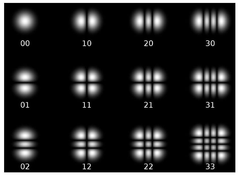
FIG. 10. Hermite-Gaussian nm modes. These are roughly rectangular arrays of 'rows' and 'columns'.
图10. 厄米特-高斯 nm 模式。这些大致呈现为具有个"行"和个"列"的矩形阵列。
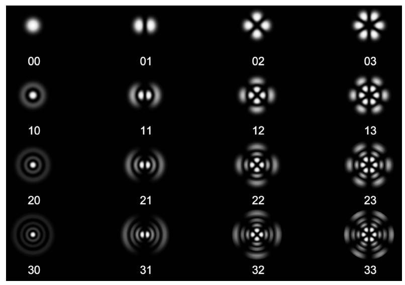
FIG. 11. Laguerre-Gaussian nm modes. These are the cyclindrical equivalent of Hermite-Gaussian modes with () equivalently divided 'sectors' and () 'rings'.
图11. 拉盖尔-高斯 nm 模式。这些是厄米特-高斯模式在圆柱坐标系中的等价形式,具有()个等分的"扇区"和()个"环"。
presented below.
如下所示。
Piezo-Controller 压电控制器
As a way of carefully iterating through the excited modes, a piezo-controller is attached to the silvered mirror in the cavity system. This piezo-controller carefully displaces the mirror according to the applied voltage. By applying a triangle wave of 2 V peak-to-peak with frequency .15 Hz, we are able to manually iterate through the various transverse states by slightly changing the length of the cavity and thus the accepted longitudinal frequency of the cavity.
作为仔细迭代激发模式的一种方法,一个压电控制器被安装在腔体系统中的镀银镜上。这个压电控制器根据施加的电压精确地移动镜子。通过施加峰峰值为2 V、频率为0.15 Hz的三角波,我们能够通过轻微改变腔体的长度来手动迭代各种横向状态,从而改变腔体可接受的纵向频率。
In theory, we should be able to see peaks in the intensity output as the frequency is swept across the various modes (including the dominant mode) from which we could determine parameters of the cavity such as the finesse and quality factor. However, in practice, the beam that exits the cavity at the output back-polished mirror is incredibly dim in intensity with the photodiode output on the order of 100 s of microvolts. Although the Gaussian modes are swept over by the piezocontroller with periods of bright and dim intensities, the changes in intensity are so small that it could not be accurately resolved by the oscilloscope.
理论上,当频率扫过各种模式(包括主要的模式)时,我们应该能够在强度输出中看到峰值,从中我们可以确定腔体的参数,如精细度和品质因数。然而,在实践中,从输出背面抛光镜处离开腔体的光束的强度极其微弱,光电二极管输出仅为数百微伏量级。尽管高斯模式被压电控制器以明暗交替的强度周期扫过,但强度的变化太小,以至于示波器无法准确分辨。
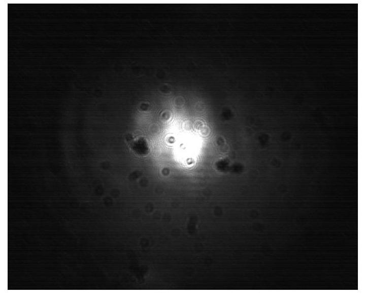
FIG. 12. Laguerre-Gaussian 00 mode.
图12. 拉盖尔-高斯 00 模式。
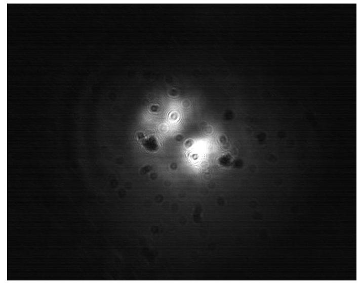
FIG. 13. Laguerre-Gaussian 01 mode.
图13. 拉盖尔-高斯 01 模式。
CONCLUSION 结论
This paper has explored the nature of Gaussian beams and how they evolve in different optical systems through the use of the complex beam parameter and ray transfer matrices. We have seen how Gaussian beams incident on the core of step index fibers can be transmitted with high efficiency by utilizing total internal reflection. We have also described the mechanics of optical cavities, the criteria for stability and the various transverse modes that they capture. In the process, we have gained a powerful understanding of how the Gaussian beam parameters necessary to transmit light in optical fibers and stabilize modes in optical cavities can be precisely constructed using only typical optical elements such as lenses and mir-
本文探讨了高斯光束的本质,以及它们如何通过使用复光束参数和光线传输矩阵在不同的光学系统中演化。我们看到了入射到阶跃折射率光纤的纤芯上的高斯光束如何通过利用全内反射实现高效率传输。我们还描述了光学腔的力学特性、稳定性的标准以及它们捕获的各种横向模式。在这个过程中,我们深入理解了如何仅使用透镜和镜子等典型光学元件来精确构建在光纤中传输光和在光学腔中稳定模式所需的高斯光束参数。
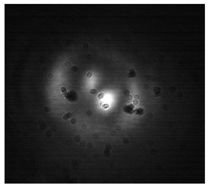
FIG. 14. Laguerre-Gaussian 11 mode.
图14. 拉盖尔-高斯 11 模式。
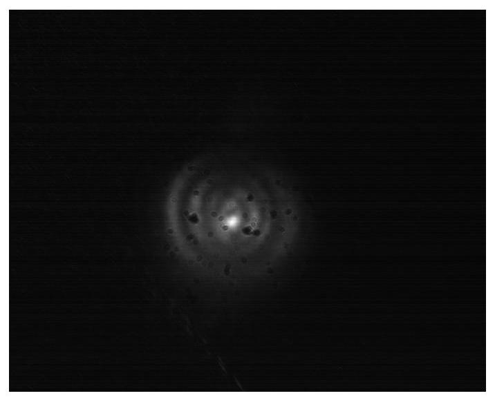
FIG. 15. Laguerre-Gaussian 31 mode.
图15. 拉盖尔-高斯 31 模式。
rors. With these tools at our disposal we are now fully capable of designing and analyzing increasingly complex optical systems.
子等工具。有了这些工具,我们现在完全有能力设计和分析日益复杂的光学系统**。
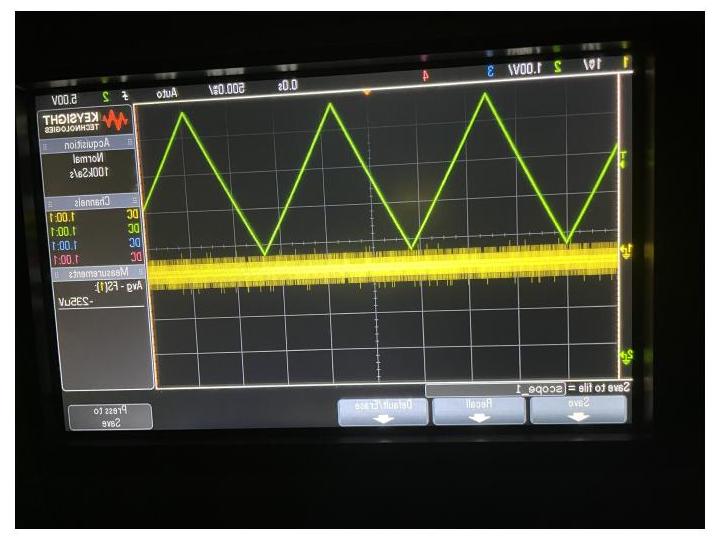
FIG. 16. Oscilloscope readout of the piezo-controller input voltage (green) and photodiode readout of the cavity (yellow). The measured intensities are so small, in the order of 100s of micrometers, that different exited modes cannot be accurately resolved.
图16. 压电控制器输入电压(绿色)和腔体的光电二极管读数(黄色)的示波器读数。测量的强度非常小,在数百微米量级,以至于不同的激发模式无法被准确分辨。
APPENDIX 附录
Beam Waist Measurement 光束束腰测量
The intensity profile of a Gaussian beam that propagates in the direction can be expressed as
在方向传播的高斯光束的强度分布可以表示为:
where and are the x and y components of the beam waist respectively. Suppose we have a flat edge that translates along the x axis and blocks a portion of the Gaussian beam. Integrating the intensity over the exposed beam regions, we can write the power detected by a photodiode as
其中和分别是光束束腰的x和y分量。假设我们有一个沿x轴移动的平边缘,它遮挡了部分高斯光束。对暴露的光束区域的强度进行积分,我们可以写出光电二极管检测到的功率为:
where erf is the error function. That is, by translating the flat edge across the x axis and recording the respective power, we can fit the data to 17 and extract the beam waist . A similar procedure can be performed on the y axis to determine .
其中erf是误差函数。也就是说,通过沿x轴移动平边缘并记录相应的功率,我们可以将数据拟合到方程17并提取光束束腰。类似的程序可以在y轴上执行以确定。